Half Adder And Full Adder Circuit
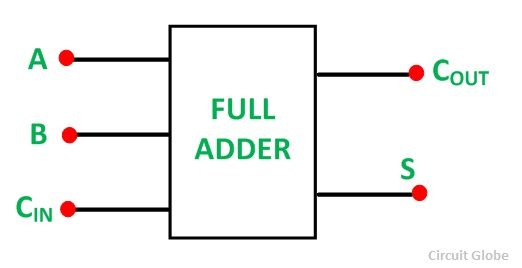
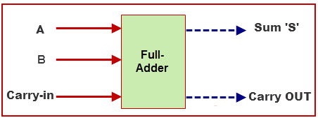
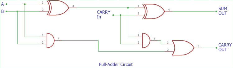
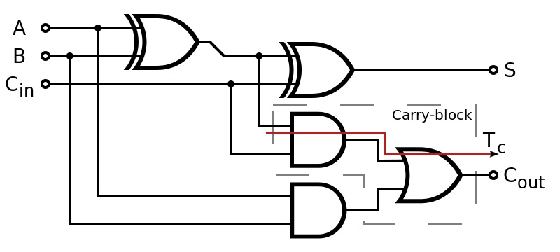
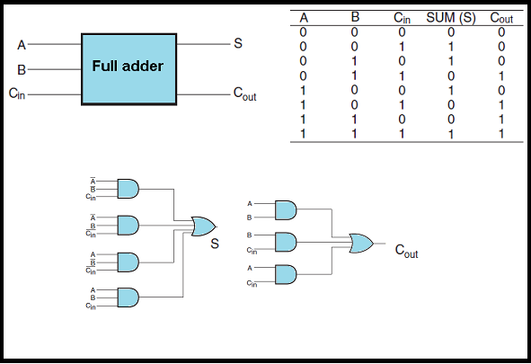
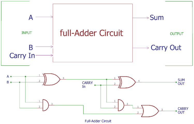
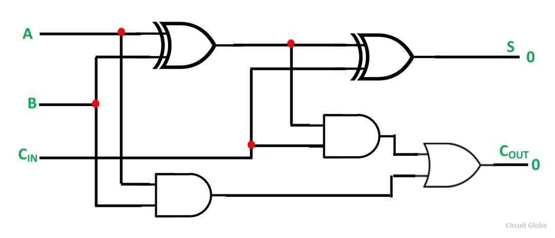
Finally the output s is obtained. The full adder is a logical circuit that performs an addition operation on three binary digits and just like the half adder it also generates a carry out to the next addition column.
 What Is Half Adder And Full Adder Circuit Circuit Diagram
Two of the three bits are same as before which are a the augend bit and b the addend bit.
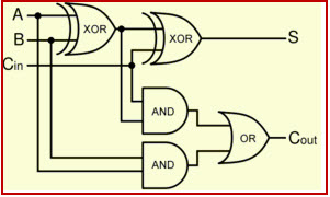
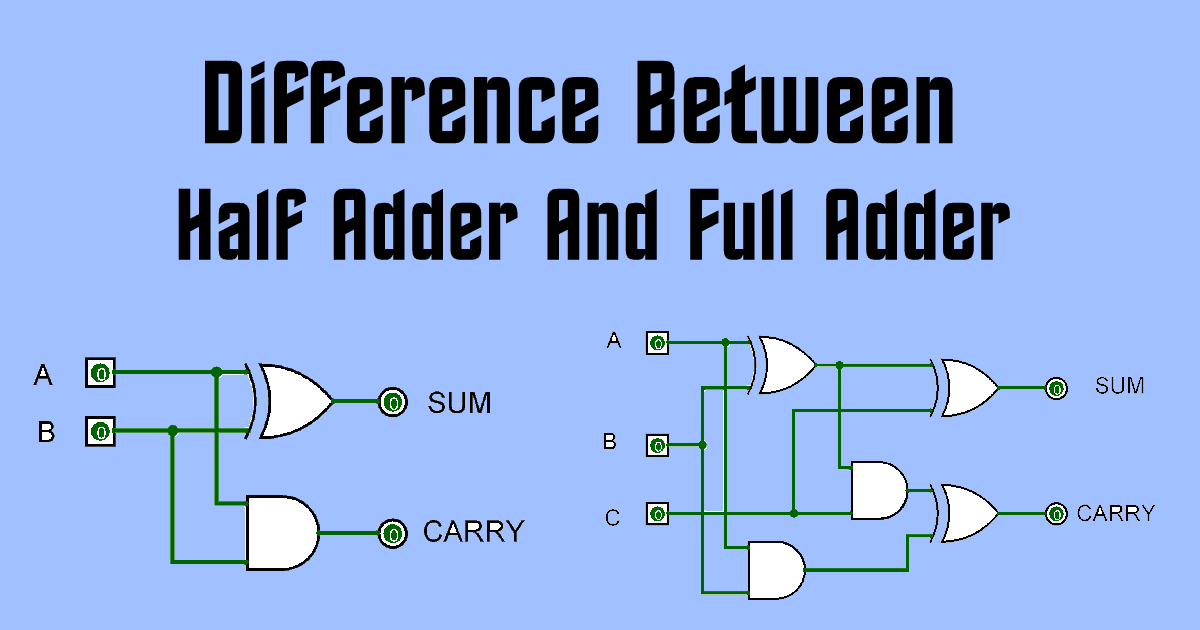
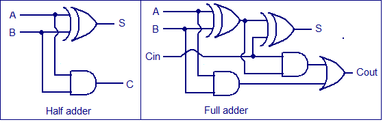
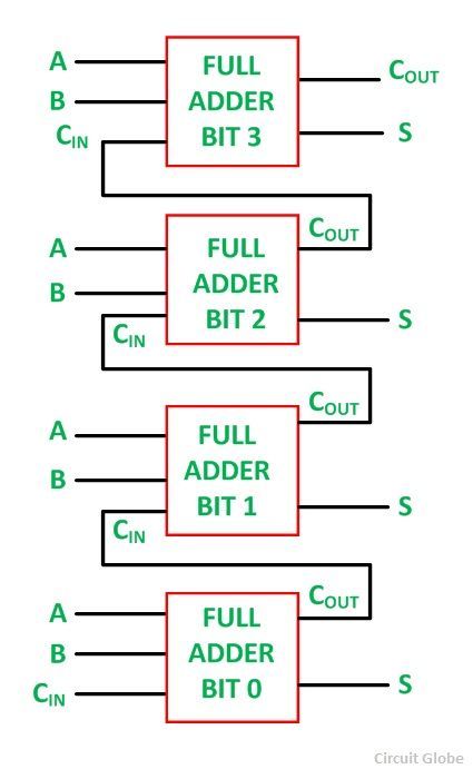
Half adder and full adder circuit. Full adder is a digital circuit used to calculate the sum of three binary bits which is the main difference between this and half adder. For example if we want to implement a 4 bit adder circuit we can combine 1 half adder and 3 full adder. A and c which add the three input numbers and generate a carry and sum.
Adders are divided into two categories namely half adder and full adder circuit. With our easy to use simulator interface you will be building circuits in no time. Full adders are complex and difficult to implement when compared to half adders.
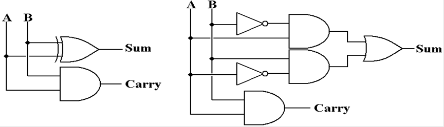
Explore digital circuits online with circuitverse. This article gives brief information about half adder and full adder in tabular forms and circuit diagrams. Also the figure below represents the circuit of half adder using nand gate only.
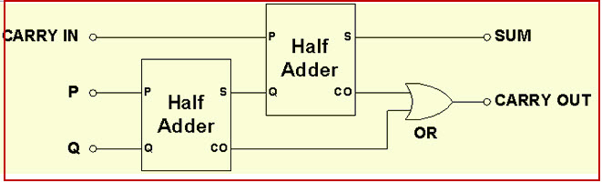
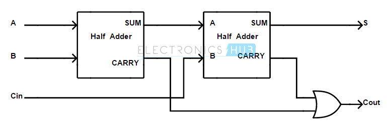
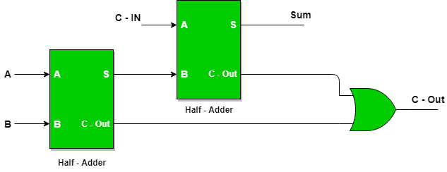
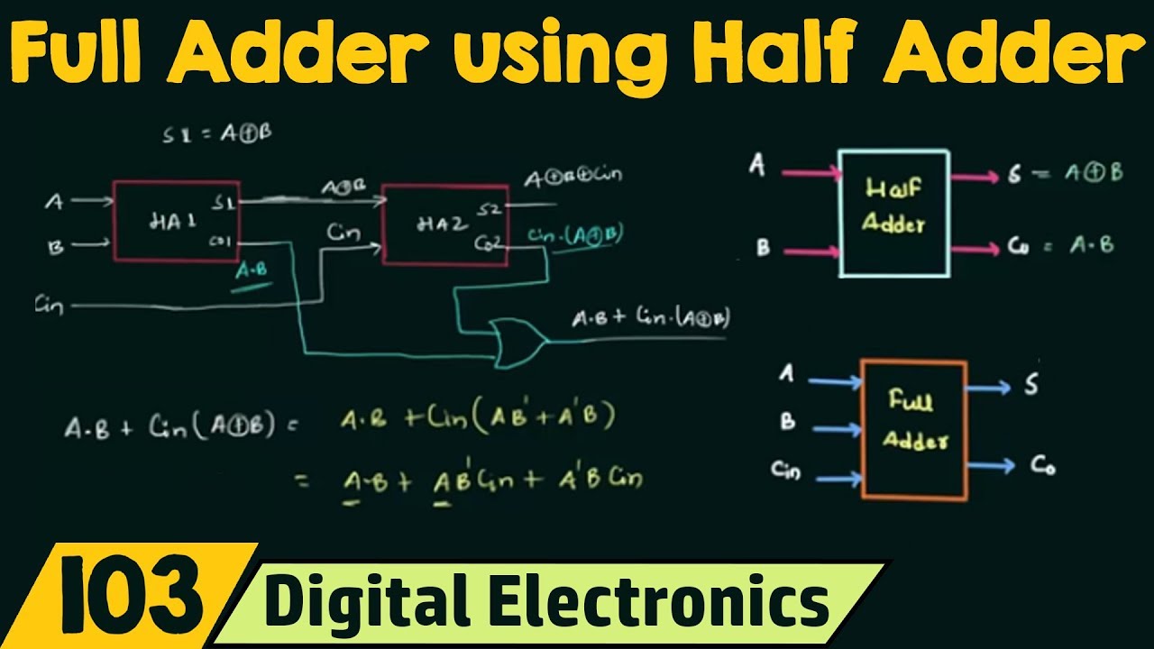
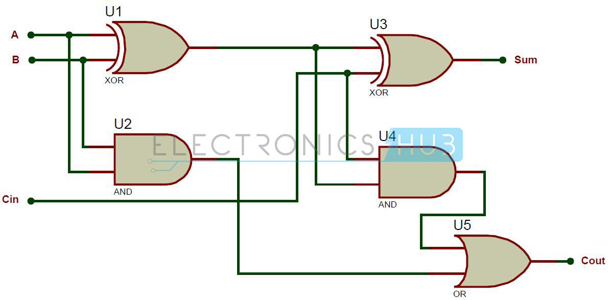
Difference between half adder and full adder circuit definition. Half adder and full adder circuit. Thus a full adder circuit can be implemented with the help of two half adder circuits.
The first will half adder will be used to add a and b to produce a partial sum. Then a carry in is a possible carry from a less significant digit while a carry out represents a carry to a more significant digit. The first half adder circuit will be used to add a and b to produce a partial sum.
Thus we can implement a full adder circuit with the help of two half adder circuits. Let us have a look at the circuit representation of half adder using only nor gate. The second half adder logic can be used to add c in to the sum produced by the first half adder circuit.
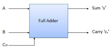
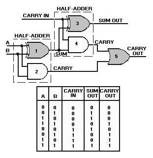
The full adder circuit has three inputs. Moreover half adder has two operands as the input a b while full adder has two operands a b and carry bit. If any of the half adder logic produces a carry there will be an output carry.
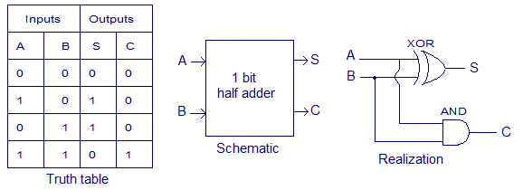
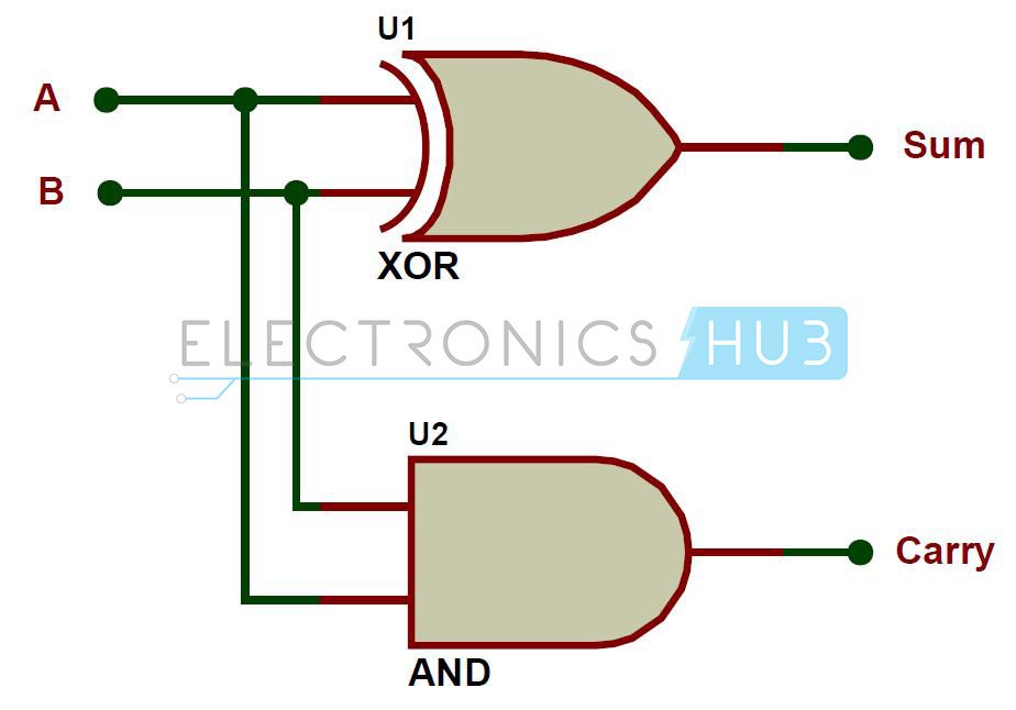
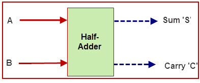
Multi digit adder circuit after looking at the binary addition process half adder circuit and full adder circuit now we can build a multi digit binary adder by combining the half adder and full adder circuit. So from the above discussion it is clear that adders perform the addition of bits but half adder can only add single bit numbers. The half adder circuit has two inputs.
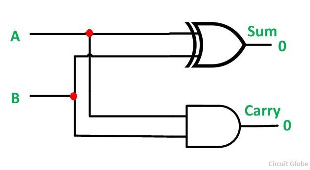
A and b which add two input digits and generate a carry and sum. A half adder is an adder circuit that adds two single binary digits and provides the sum and the carry bit. The second half adder logic can be used to add cin to the sum produced by the first half adder to get the final s output.
Therefore for the addition of more than single bit numbers full adders are used.
 Half Adder And Full Adder Circuit With Truth Tables
 Half Adder And Full Adder Circuit Truth Table Full Adder Using
 Full Adder Circuit Theory Truth Table Construction
 Interactive Circuits For Half Adder And Full Adder Download
 Half Adder And Full Adder Circuit With Truth Tables
 Full Adder Circuitverse
 4bitadder Solutionaire
 Half Adder And Full Adder Circuit With Truth Tables
 Half Adder And Full Adder Circuits Using Nand Gates
Half Adder And Full Adder Circuit With Truth Tables
 Implementation Of Full Adder Using Two Half Adder And Or Gate
 Half Adder And Full Adder Circuits Using Nand Gates
 Half Adder And Full Adder Circuit Truth Table Full Adder Using
 Difference Between Half Adder And Full Adder Ahirlabs
 Full Adder In Digital Logic Geeksforgeeks
 What Is Half Adder And Full Adder Circuit Circuit Diagram
 Ripple Carry Adder 4 Bit Ripple Carry Adder Circuit Propagation
Https Encrypted Tbn0 Gstatic Com Images Q Tbn 3aand9gcq45nnilzkw24cjuvae2d1u4xga2irjpabwopkrckemofap2lja Usqp Cau
 Binary Adder And Binary Addition Using Ex Or Gates
 Half Adder And Full Adder Circuit With Truth Tables
 How To Design A Full Adder Using Two Half Adders Quora

 Full Adder Using Half Adder Ardusat Org
 What Is Half Adder And Full Adder Circuit Circuit Diagram
 What Is Half Adder Adder Circuit Digital Circuit De 18 Youtube
 Half Adder And Full Adder Circuit Truth Table Full Adder Using
 Full Adder Using Half Adder Youtube
What Is The Major Difference Between Half Adders And Full Adders


 Practical Electronics Adders Wikibooks Open Books For An Open World
 Full Adder Circuit Theory Truth Table Construction
 What Is Half Adder And Full Adder Circuit Circuit Diagram
 Half Adder And Full Adder Circuits Using Nand Gates
 Binary Adder And Binary Addition Using Ex Or Gates
Posting Komentar
Posting Komentar