Half Adder And Full Adder Truth Table
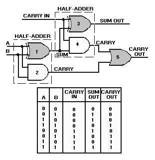
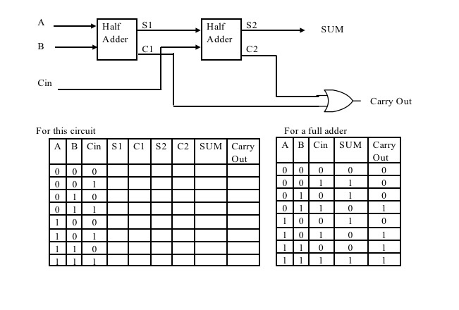
In many computers and other types of processors adders are used to calculate addresses similar operations and table indices in the alu and also in other parts of the processors. Thus a full adder circuit can be implemented with the help of two half adder circuits.
An adder is a digital logic circuit in electronics that implements addition of numbers.

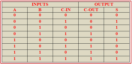
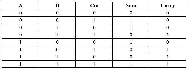
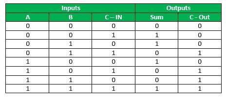
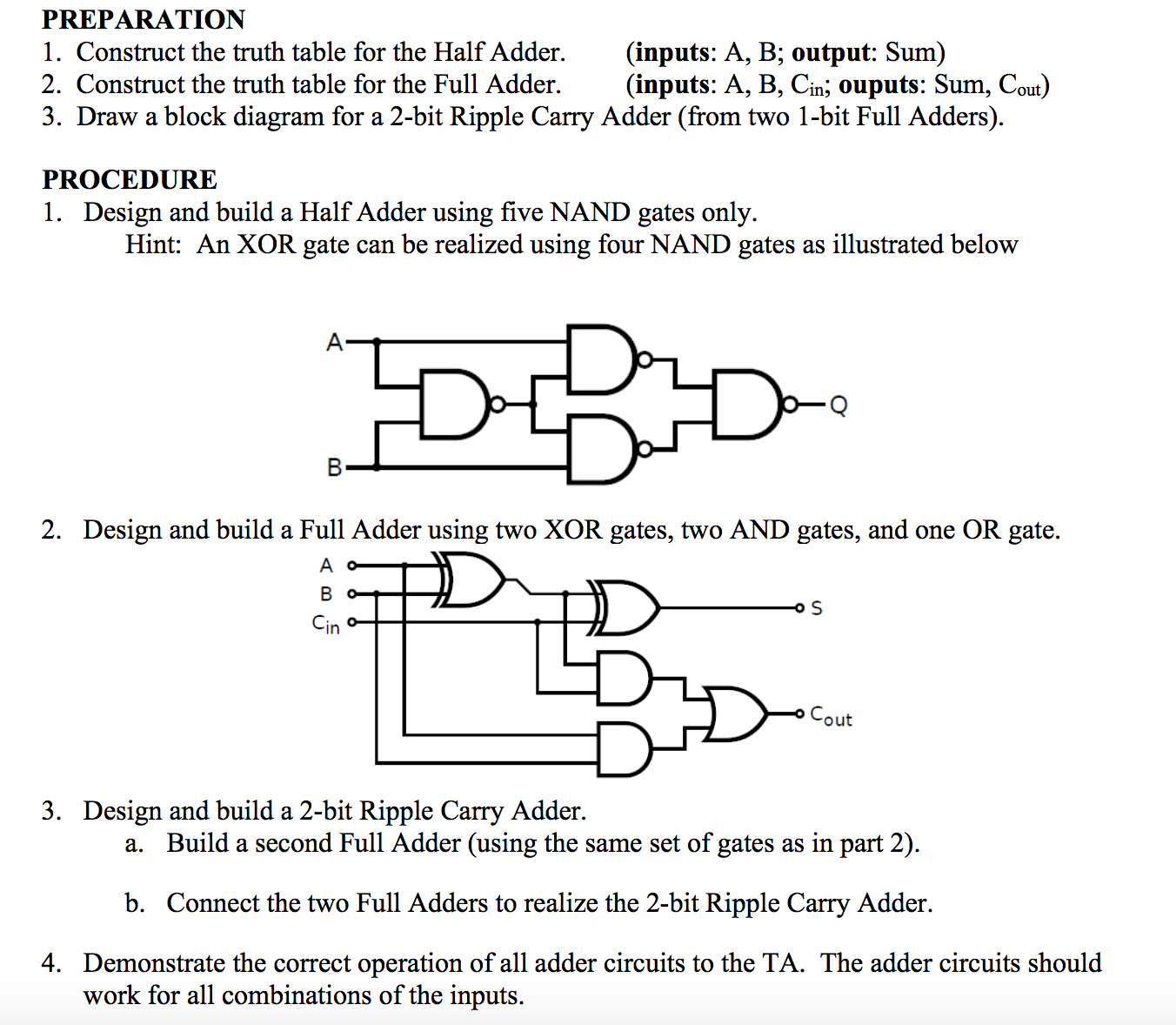
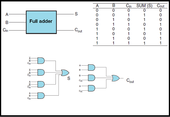
Half adder and full adder truth table. A b and c in which add three input binary digits and generate two binary outputs i e. We can see that the output s is an exor between the input a and the half adder sum output with b and cin inputs. The half adder truth table shown in 3 6 gives the relation between input and output variables for half adder circuit operation.
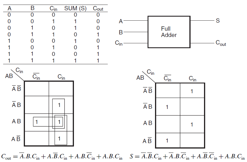
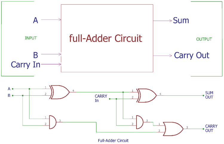
K map simplification for carry and sum. A full adder can also be implemented with two half adders and one or gate as shown in the fig. The c out will be true only if any of the two inputs out of the three are high or at logic 1.
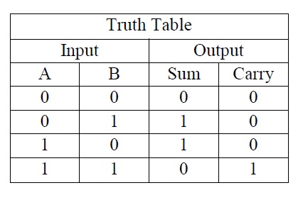
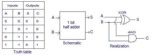
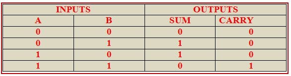
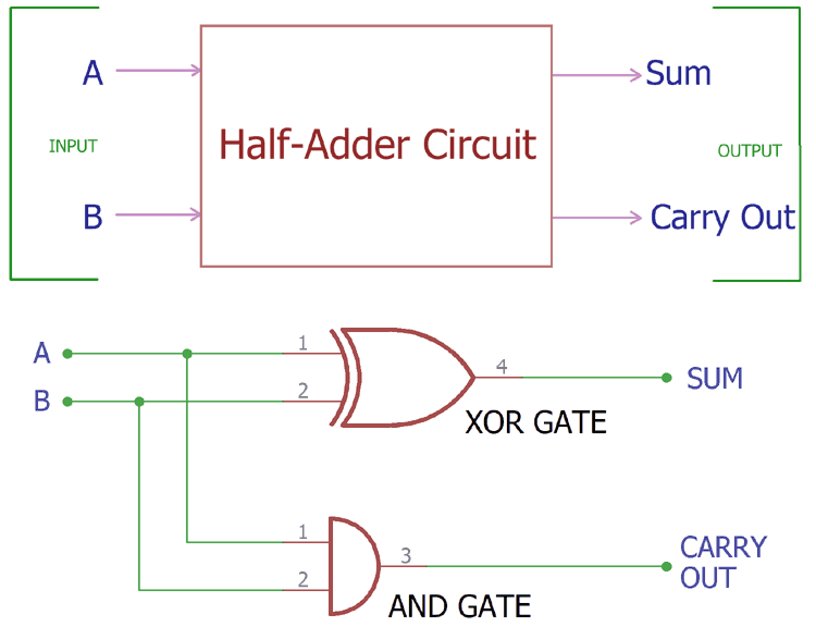
Half adder is a combinational arithmetic circuit that adds two numbers and produces a sum bit s and carry bit c both as the output. K map for half adder. The half adder is the simplest of all adder circuits.
What is a half adder. Adders are divided into two categories namely half adder and full adder circuit. Now by considering the truth table for half adder one can have the desired k map for both sum and carry bit.
An adder is a digital logic circuit in electronics that performs the operation of additions of two number. And while writing the desired result the position weight is neglected. Augend and addend bits.
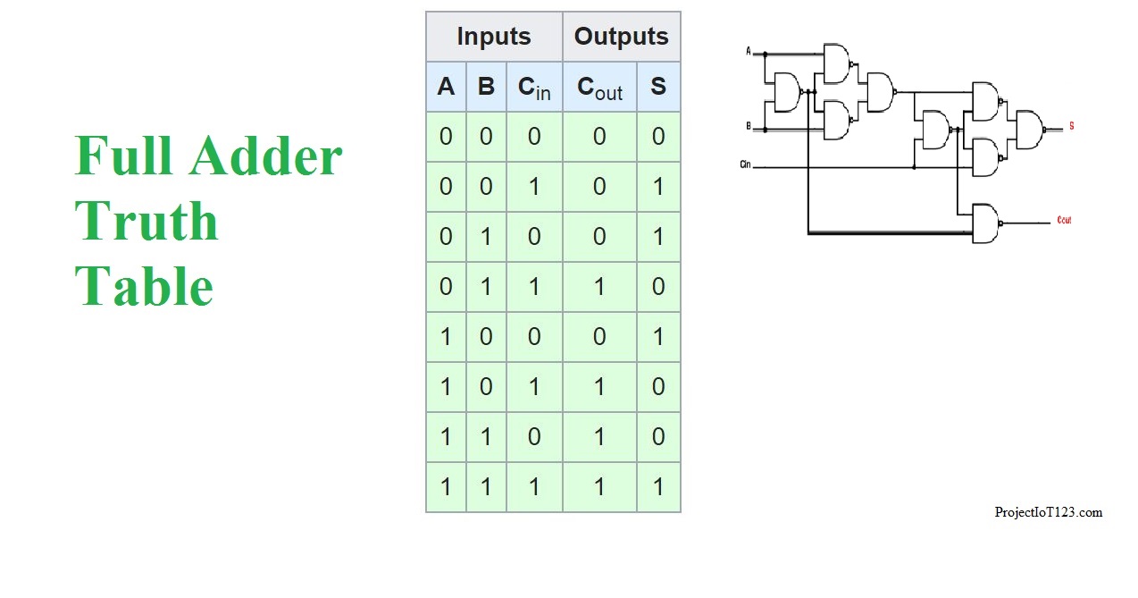
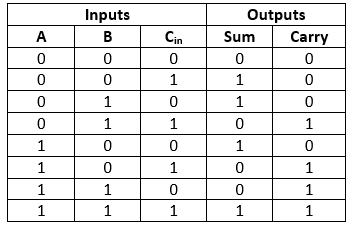
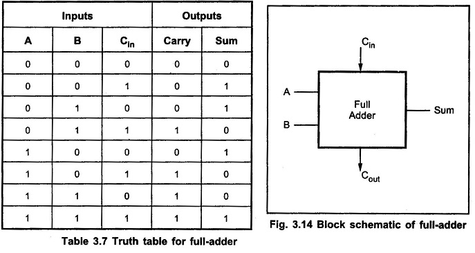
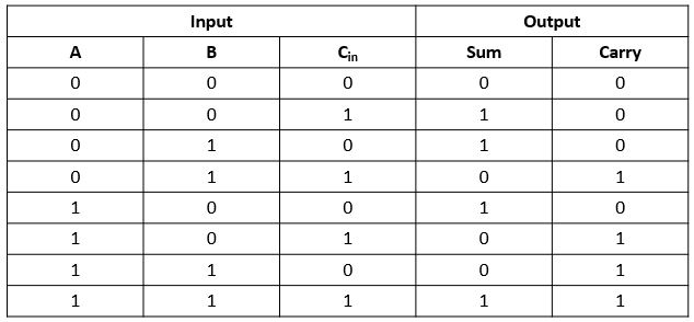
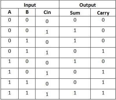
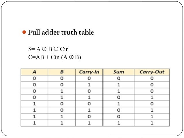
So we can implement a full adder circuit with the help of two half adder circuits. The output s is an ex or between the input a and the half adder sum output b. The truth table of the full adder circuit is shown below.
And two binary outputs. Full adder using two half adder. With the truth table the full adder logic can be implemented.
The full adder fa circuit has three inputs. The sum output from the second half adder is the exclusive or of c in and the output of the first half adder giving. A digital electronic circuit that functions to perform the addition on the binary numbers is defined as half adder.
This is the reason why we get 0 as the sum of 1 and 1 and 1 as the carry. There exists only 0 and 1 in the binary numbering system. You can see that the output s is an xor between the input a and the half adder sum output with b and c in inputs.
We must also note that the cout will only be true if any of the two inputs out of the three are high. We take c out will only be true if any of the two inputs out of the three are high. Let us consider two inputs bits a and b then sum bit s is the x or of a and b and the carry bit c will be the and of a and b.
So in this way the circuit of a half adder operates. And the carry output is. The process of addition is denary the sole difference is the number system chosen.
Adders are classified into two types. Half adder and full adder. From the above truth table the full adder logic can be implemented.
Half adder truth table. The half adder circuit operation needs two binary inputs.
 Full Adder
Half Adder Full Adder
 Introduction To Full Adder Projectiot123 Technology Information
 Half Adder And Full Adder Circuit With Truth Tables
 Truth Table For Half Adder Download Table
 2 Bit Full Adder A Schematic Of An N Bit Full Adder Constructed
 Half Adder And Full Adder Circuit With Truth Tables

 Full Adder Combinational Logic Circuits Electronics Tutorial
 Full Adder Javatpoint
 Half Adder And Full Adder Circuits Using Nand Gates
What Is A 2 Bit Full Adder Truth Table Quora
 Full Adder Circuit Theory Truth Table Construction
 Full Adder In Digital Logic Geeksforgeeks

 3xgn0g2yebpoam
 The Truth Table Of 1 Bit Full Adder Download Scientific Diagram
 Addition 2 Outline Full Adder 3 Bit Adder 2 S Complement
 Flintgroups What Is Meant By Arithmetic Circuits
 What Is A 2 Bit Full Adder Truth Table Quora
Https Encrypted Tbn0 Gstatic Com Images Q Tbn 3aand9gcsg2nmgh9ipcdr7vvnp Apzcsz8mz1tn0qw2vznxedaxaiv0uui Usqp Cau
 Full Adder Truth Table Logical Expression Circuit Youtube
 Full Adder Truth Table Logic Diagram Electricalvoice
 Binary Arithmetic Circuits
 Half Adder And Full Adder Circuits Using Nand Gates
 Solved Construct The Truth Table For The Half Adder Inp
 Half Adder And Full Adder Circuit With Truth Tables
 Cv 5390 The Full Adder May Be Constructed Using A Pair Of Half
 Full Adder Using Half Adder Ardusat Org
 Verilog Coding Tips And Tricks Verilog Code For Full Adder Using
 Half Adder Circuit Theory Truth Table Construction
 Full Adder Circuit Truth Table And Verilog Code Youtube
 Binary Adder And Binary Addition Using Ex Or Gates

 Half Adder Full Adder
Posting Komentar
Posting Komentar